


Bearing floors
All information on this page is copied material from Gulvfakta, which is a technical reference material, Source: Gulvfakta
Load-bearing wooden floors are floors that rest on a linear support of joists or beams. The load of the floor is transferred through the boards to the underlying joists or beams. The thickness of the floorboards is determined by the expected load and the distance between joists or beams.
1.7.3.1 Checklist for laying
1.7.3.2 Planning
1.7.3.3 Scattering - methods
1.7.3.4 Board, thickness and material
1.7.3.5 The beams - material
1.7.3.6 Spacing distances
1.7.3.7 Blockages
1.7.3.8 Laying of screed floors
All information on this page is copied material from Gulvfakta, which is a technical reference material, Source: Gulvfakta
How are joists built up?
Beams are built up on an underlying construction of, for example, concrete, lightweight concrete or wood, so that a level surface is achieved for the wooden floor.
Beams are included in wooden beam layers above crawlspaces and in floor separations. Both beams and layers of wooden beams offer good opportunities for placing sound and heat insulating materials in the cavity under the wooden floor. The cavity can also be used for moving heating and electrical installations.
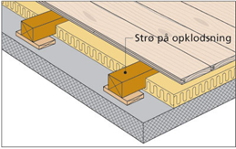 Fig. 10. Bearing floor on joists.
Load-bearing wooden floors can be made of boards or long-strip parquet. The boards can either be traditional floorboards made of solid wood, or they can be designed as parquet boards or slatted boards. Long poles are parquet poles of extra length
1.7.3.1 Checklist for laying floors
Checklist for laying floors on beams and joists:
• The relative humidity in the building must be between 35 and 65%, depending on the season, and the temperature approx. 20°C
• The building must be closed and the heating system must be installed and in use
• The moisture content of concrete, lightweight concrete, etc. must be in equilibrium with the relative humidity normal for the season. Depending on the drying conditions, this may take several months
• Insulation materials, etc. must be dry
• Brickwork made with concrete must be hardened and dry
• Moisture barrier, e.g. in the form of a 0.20 mm polyethylene foil, must be laid out before laying the floor to protect against moisture from underlying concrete or lightweight concrete structures
• Wooden floor materials must have a moisture content of 8 ± 2%, of which 2/3 of the lot should be between 7 and 9% moisture content
• Wooden floor materials dried to the conditions of use should not be unpacked before laying
1.7.3.2 Planning
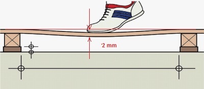
Floors laid on beams and joists must have a strength and stiffness that must be adapted to their use. Bending from loads such as shelving etc. must not be bothersome and vibrations as a result of normal walking should not occur. The floor is normally considered to be sufficiently rigid if the deflection during normal walking on the floor or a static load of 750 N is less than 2 mm (measured with a 2 meter straight beam). The deflection is measured either in the middle between two layers of bedding and/or directly on top of a bedding, between 2 blocks. If the floor is built up on the so-called sound tiles, there will be a greater deflection.
Since floors laid out on joists are not normally considered part of the load-bearing structure (due to the low installation height), the floors must therefore simply comply with the stiffness requirements. Note, however, that floors laid out on joists can be considered load-bearing.
Floor boards that are to be used in load-bearing structures must be able to meet the requirements of, among other things, in accordance with EN 1991. payloads see the table below (1).
| Load category | Surface load Q k (kN/M 2 ) | Point load Q k (kN) | |
| A1 | Housing and internal access roads | 1.5 | 2.0 |
| B | Office and light business | 2.5 | 2.5 |
| C1 | Gathering room with table arrangement | 2.5 | 3.0 |
| C2 | Meeting room with fixed seating | 4.0 | 3.0 |
| C3-C5 | Assembly rooms without fixed seating | 5.0 | 4.0 |
| D1 | Smaller shops | 5.0 | 7.0 |
| D2 | Larger stores | 5.0 | 4.0 |
| Access roads to category B, C and D up to: | 5.0 | 4.0 |
(Table 1)
When designing/dimensioning a screed floor, there are several factors that must be taken into account.
The most important are:
• Terminations against walls and other edges
• Thickness and material of the boards
• Distance between beams, material and cross-sectional dimension
• The distance between the blocks
1.7.3.3 Scattering - methods
It is often along walls etc. that the user experiences a lack of rigidity in the floor construction. The explanation is often to be found in the way we furnish the rooms, combined with the way the floor structure is built. In order to give the floor sufficient rigidity, it is necessary to either lay extra auxiliary joists along the walls of the room or to reduce the joist distance in general in the room. In figures 1, 2 and 3, three methods of stone laying are illustrated.
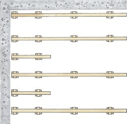 Method 1 - Insertion of auxiliary spreaders
Fig. 1: Along walls parallel to the screed line, lay 1st screed so that the distance to the wall is 50 - 80 mm. The 2nd screed is laid a maximum of 400 mm from the 1st screed. Other joists are laid at normal distances. When wicking is perpendicular to the direction of the straw, a short intermediate straw is inserted.
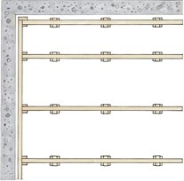 Method 2 - Edge joists
Fig . 2: As with method 1, the distance between the 1st & 2nd screed is reduced to a maximum of 400 mm. Above the ends of the joists, an edge joist is placed, which is attached to the joists with oblique screws so that a firm and stable frame is obtained. Blocks are placed under the joints between the main and edge joists or under the edge joists.
 Method 3 - Reduced litter spacing.
Fig. 3: This method is recommended for smaller rooms. The litter spacing is reduced to 70% of the litter spacing that would normally be used in the room. Whereby help and edge joists can be omitted.
1.7.3.4 Board thickness and material
Solid boards for laying on joists (and joists) must have a thickness of at least 20 mm so that the overall floor construction has the necessary stiffness and strength. Experiments show that the strength of floors made of softwood boards can be compared to the strength of parquet boards made of hardwood. Hardwood is basically stronger than softwood, but the strength of a parquet board made of hardwood is weakened as a result of the many joints. Slatted boards for laying on joists must have a thickness of at least 22 mm. For lamellar parquet boards, the thickness and design of the backside definer is very decisive for the strength of the board. The backside definer must be made in one continuous piece and be at least 2 mm, preferably 3 mm thick.
1.7.3.5 The beams - material
Beams can be made of solid or laminated wood. Beams of solid wood must be sharp-edged battens with a width of at least 45 mm (planed measurement). Beams in laminated wood (e.g. Kerto) must have a width of at least 40 mm, then there is no risk of splitting. The joists should be supplied as long as possible, as the best results are achieved with full-length battens. Lengths of up to 3.9 m are normal stock, and longer lengths - up to 4.8 m - can usually be delivered to order. Joists should at least be planed on the side facing the floorboards.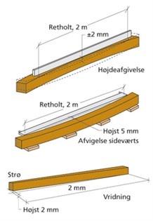 Beams - correctness
Figure 11. Tolerances on joists.
The joists must be so straight that their surface after laying deviates by no more than ± 2 mm on a 2 m straight beam. After laying, there should be no more than 5 mm lateral deviations from straightness of 2 m (deviation from straight timber placed on the hollow side of the screed). The joists must not twist more than, when laid loosely with one end held against the floor, a maximum "gap" of 2 mm per 2 m joist length at a corner at the opposite joist end. For a screed of e.g. 3.9 m, this corresponds to the twisting leading to a "gap" of approx. 4 mm.
The joists must be of a quality so that the requirements for studs correspond to the sorting rules for DK 18. This means that single studs must make up no more than 1/3 x the cross-sectional area and stud groups no more than 1/2 x the cross-sectional area. The best result is achieved if the moisture content of the joists at the time of laying corresponds to that of the boards. This reduces i.a. problems with the squeak. The moisture content of the screeds must never exceed 12% when laid. This means that the average of the measurements taken must not exceed 12%, and that there should not normally be individual results higher than 14%.
1.7.3.6 Spacing distances
In terms of experience, you will get satisfactory stiffness by using the normal distances between the joists specified in table 2 ("Strøning and installation distances"), provided that you use laying methods 1 and 2, described under "Strøning - methods".
If method 3 is used, ALL distances must be reduced to 70% of the normal distance
Table 2: Spacing and mounting distances
| Load class | A1 | B | C1, C2 | C3-C5 |
| Type | Residence | Office | Meeting room with fixed seating | Assembly rooms without fixed seating |
| Point load | 2 kN | 2.5 kN | 3.0 kN | 4.0 kN |
| Spacing of studs at different board thicknesses | ||||
| Board thickness = 20mm | 520 | - | - | - |
| Board thickness = 22mm | 600 | 530 | - | - |
| Board thickness = 25 mm | 720 | 640 | 590 | 510 |
| Board thickness = 28 mm | 850 | 760 | 700 | 600 |
| Board thickness = 30 mm | 950 | 850 | 770 | 670 |
| 22 mm Laminate parquet with 3 mm underside veneer | 500 | 450 | - | - |
| 22 mm Laminate parquet with 2 mm underside veneer | 460 | 320 | - | - |
| Blocking distance for different litter dimensions and litter types | ||||
| Sawn softwood in dimension 38 X 56 mm | 550 | - | - | - |
| Sawn softwood in dimension 38 X 73 mm | 600 | 560 | - | - |
| Sawn softwood in dimension 45 X 45 mm | 600 | 560 | - | - |
| Sawn softwood in dimension 45 X 70 mm | 700 | 650 | 610 | 550 |
| Sawn softwood in dimension 70 X 45mm | 930 | 870 | 820 | 740 |
| Saw-cut needlewood in dimension 70 X 70mm | 1080 | 1000 | 950 | 860 |
| Sawn softwood in dimension 95 X 45 mm | 1270 | 1180 | 1110 | 1010 |
| Laminated wood dimension 39 X 40 mm | 530 | 490 | 460 | - |
| Laminated wood dimension 63 X 40 mm | 850 | 790 | 740 | 670 |
| Laminated wood dimension 75 X 40 mm | 1010 | 940 | 880 | 800 |
For the instructions in the above table, the following is assumed:
For conifers and hardwoods without end grooves:
• That butts/end joints in softwood floorboards are placed on top of joists or beams (no plane joists)
• That, at most, every 3rd softwood board is butted/assembled on top of the same joist/beam, i.e. that there is min. 2 boards in between 2 end joints on the same joist/beam.
• That the board spans over min. 2 subjects
For hardwood and softwood with end groove:
• That flying shocks are found for every 3rd board within the same subject at most, i.e. that there is min. 2 boards in between 2 end joints in the same section.
• That flying strikes in the same row of boards do not occur in two neighboring subjects.
• That air strikes do not occur in the first and last row
• That end joints are glued in tongue and groove
The specified distances ensure a reasonably rigid floor that does not cause annoying vibrations when walking or cause furniture and fittings to have annoying slopes due to the bending of the floor. The support distance depends on the chosen material thickness and the expected load.
Beam layers that are used as a base for load-bearing wooden floors must be trimmed to a flat surface or created by lining on top or on the side of beams. Moisture content in the beams must therefore be no more than 13%. This means that the average of the measurements taken must not exceed 13%, and that there should not normally be individual results higher than 15%. The instructions in table 2 also apply to joists.
1.7.3.7 Blockages
The beams are created to a flat surface using various blocks. The distance between the blocks can be seen in table 2 under the section about screed distances.
Brickwork for joists can be carried out by:
• Plywood, at least 100 cm2, eg 100 x 100 mm or 80 x 125 mm.
• Chipboard, at least 100 cm2, eg 100 x 100 mm or 80 x 125 mm.
• Hard wood fiber board, at least 100 cm2, eg 100 x 100 mm or 80 x 125 mm.
• Plastic wedges.
For higher supports, e.g. special plastic wedges or a base of brick or concrete can be used, on which the final brickwork is placed.
Plastic wedges for building blocks must have documentation for testing lifetime and load, so that there is security for their long-term properties. Plastic wedges of unknown quality can, according to experience, lead to settlements in the brickwork. Soft pieces, can be used under blocks to improve step sound absorption. Most building systems can provide "sound chips" as an integral part of the system. Be aware that the use of sound tiles will make the floor more yielding, resulting in greater deflections. The larger bends are more clearly seen along edges and especially in corners. The deflection will depend on the material of the selected sound chip.
Asphalt cardboard is used under brickwork as a robust layer that provides extra security against mechanical overload of the moisture barrier while also being moisture-tight. For example, brickboard can be used in strips of 200 mm width, which can be cut into square pieces of 200 x 200 mm. Asphalt cardboard can be used as an underlay for floating floors as protection against building damp or rising ground damp, in the quality under cardboard PF 2000.
1.7.3.8 Laying screed floors
Before laying a screed floor, you must check that the materials and premises comply with the specifications, see section 1.4.0.6 for further information about this. As well as deciding which sprinkling method you want to use (for further description, click here). Laying a screed floor starts with the laying of the screeds. The beams must be as long as possible and preferably without joints. If joints are necessary, they must be supplemented with extra blocks and the distance between the blocks around the joint must be reduced by at least 10%. The assemblies must be staggered and distributed so that there is min. two mounting distances between each joint. The joints can also be done using laskers. The laskers must be mine. 300 mm long, made of good material, e.g. 12 mm structural plywood, see also figure 1
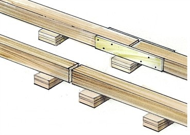 Fig. 1
Above the ends, the beams must hold approx. 10 mm distance to walls etc. It may be necessary to cut out the screed to make room for heating pipes etc. In such cases, there must be a minimum 10 mm free distance for the installation. If there is a cut in the screed, extra brickwork must be carried out. See also Figure 2
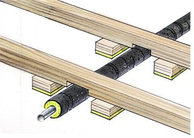 Fig. 2
The joists are created before laying the wooden floor to a flat surface by adjusting the block heights. Flatness is checked using a 2 meter straightedge, see also the section "Flatness and floors" for further information about this area. If a certain level height is to be maintained, the heights can advantageously be set with a laser or a liquid leveling device. When determining the height, you must also focus on the floor's connections to other building parts, e.g. terminations in doors etc. If the screed floor is to go unbroken through one or more doors, there must be extra focus on laying out and straightening the screeds by the doors.
If the floor is to be laid without connection to other rooms, the boards are laid lengthwise of the house. The first row of boards is laid with the groove side against a wall. Since the walls are rarely sufficiently straight, the first row is created after a string. A dilation distance of at least 10 mm must be maintained, the easiest way to do this is by using distance blocks or wedges. For large rooms, dilation distances must be agreed with the supplier. The floorboards are attached to the joists with screws or nails. The most common is to nail or screw the boards under cover, so that the nail/screw cannot be seen. But visible nailing from above is possible and recommended by several manufacturers for wide boards (> 200 mm).