


Special constructions
All information on this page is copied material from Gulvfakta, which is a technical reference material, Source: Gulvfakta
In certain cases, there is a need to produce floors that meet very special requirements, for example: Installation floors, wet rooms, electrically conductive floor structures, sports floors and floors in laboratories and the food industry.
2.4.0.1 General
2.4.0.2 Static dissipative and static conductive floor coverings
2.4.0.3 Floors and walls in laboratory environments and the food industry
2.4.0.4 GMO laboratories
2.4.0.5 Sports floors
2.4.0.6 Moisture barrier
2.4.0.7 Underfloor heating
2.4.0.8 Installation floors


All information on this page is copied material from Gulvfakta, which is a technical reference material, Source: Gulvfakta
2.4.0.1 General
Some of these floors are made with ordinary floor coverings, while the special requirements are met by a special construction of the structure. This is, for example, the case with wet rooms, where with an "ordinary" PVC coating, a waterproof coating is carried out with a slope towards the drain, etc. In other cases, this involves the use of special products, which must also be installed in a special way, e.g. conductive coatings in operating rooms. What follows is a brief review of the overall conditions for some special constructions. For more detailed information, advice must be sought from suppliers or in specialist literature.
2.4.0.2 Static dissipative and static conductive floor coverings
Static dissipative and static conductive floors are a term for floors that can dissipate electrostatic charge. They must not be confused with antistatic floors, which do not have the same dissipative effect. Antistatic floor coverings are used to avoid electrical charging, which under certain circumstances can cause nuisance discharges when touching grounded objects. The conductive properties of floor coverings are tested in accordance with DS/EN 1081. However, the standard does not specify requirements for the resistance of the floor covering in different areas of use. It is the client or his advisor who provides any requirements for the electrostatic properties of floors. Requirements may have a background in safety regulations, for example the Working Environment Act or the High Current Order. Requirements must always be stated in the tender and agreement basis.
Coating types
Static dissipative and static conductive floors can be made with a number of floor coverings, e.g. linoleum, vinyl, rubber and textile floor coverings.
Conditions in connection with laying
Electrostatically dissipative and conductive floor coverings are usually laid in conductive adhesive. However, some floor coverings are available with a conductive back, which enables the use of ordinary glue. It must be agreed where the copper tape is to be run up the wall. Grounding must be carried out by an authorized electrician. For safety reasons, the conductivity should be checked by an impartial person - and it must also be agreed if the flooring contractor is to arrange for the check to be carried out.
Maintenance
The coating supplier's instructions on cleaning and maintenance of conductive and conductive floor coverings must be followed in order to achieve optimal dissipation effect.
Statically dissipative and statically conductive elastic floor coverings are described in more detail in the section on Elastic floor coverings.
2.4.0.3 Floors and walls in laboratory environments and the food industry
Floors and walls in laboratory environments and in the food industry can largely be designed according to the same guidelines as for wet rooms. There will often be a need for waterproof floors with a slope towards drainage.
Floor coverings in these environments are chosen based on the specific use of the room, including in particular the effect of acids, bases, organic solvents and thermal loads, etc.
With such specific requirements, the flooring should be carefully designed by the client and in close cooperation with the flooring supplier.
An important parameter for a good result is the type and nature of the substrate and that the installation of the floor covering takes place in accordance with the floor covering supplier's recommendations.
The Danish Building Agency has published an experience-based note on laboratory experiences, Surfaces in laboratories, November 2014.
In laboratory environments, floors are often required to withstand chemicals such as acids, bases and organic solvents. The floor covering supplier will normally have carried out chemical resistance tests according to the standard DS/EN ISO 26987, Resilient floor coverings - Determination of stains and resistance to chemicals.
If there are requirements for water and air tightness, it is recommended that the floor covering is GVK approved and that the work is carried out by wet room certified installers with a connection to GVK - Gulvbranchen Vådrumskontrol.
2.4.0.4 GMO laboratories
GMO (Genetically Modified Organisms) laboratories are a special type of laboratory where plants, animals, microorganisms, cell cultures and viruses are worked with, in which new compositions of the genetic material occur that do not occur naturally.
GMO laboratories are classified into 4 classes.
In GMO 1 laboratories, only work of the lowest risk may be carried out, and from class 2, 3 and 4, increasing requirements are placed on layout and safety measures. In the case of GMO 2 and above, the floor covering must be done with perforated tiles. However, it can be recommended in all categories, as greater flexibility is thereby achieved in relation to future use of the laboratory. The overall requirements for GMO laboratories can be found in Executive Order No. 910 on genetic technology and the working environment.
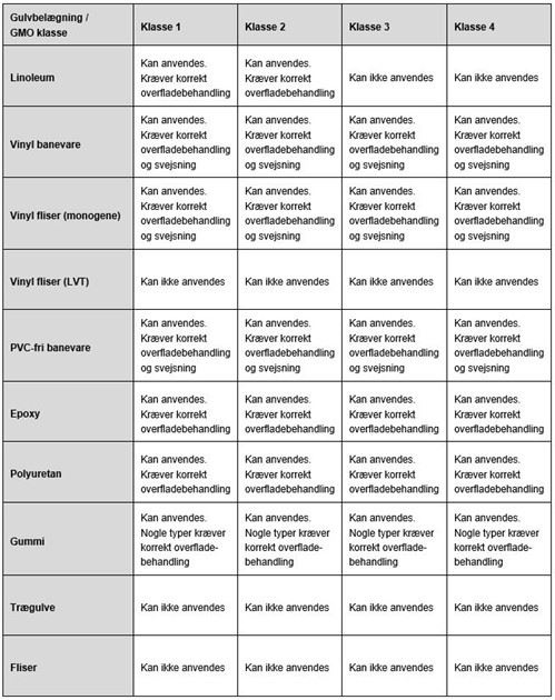
Table of applicable floor coverings in GMO laboratories that are not categorized as wet rooms.
For further information, please refer to:
• The building regulations
• AT guidance C.0.5: Risk assessment of genetic engineering research projects, etc.
• DS/EN ISO 26987, Resilient floor coverings - Determination of stains and resistance to chemicals
• BEK no. 910: Decree on genetic technology and the working environment
• Surfaces in laboratories: Experience note prepared by NNE Pharmaplan for the Danish Building Agency
2.4.0.5 Sports floors
Sports flooring is a general term for flooring for use in sports halls, gymnasiums, fitness rooms and other areas, which must be carried out according to special guidelines due to the special requirements that are set for sports activities.
A sports floor differs from ordinary floors in, for example, homes, in that the floor must be able to withstand many dynamic impacts from shocks, jumps and falls during ball games, aerobics, gymnastics, dancing and the like. The demands on sports floors are therefore high in terms of wear resistance, lifetime, maintenance and not least in relation to function. A good sports floor reduces the risk of injury for athletes by being suitably slip-resistant without having too much friction. Precisely this balance is crucial to ensure the athletes against slipping during normal movements such as running and jumping, but no more than the shoe can slip during feints and sudden twists. This reduces the risk of ankle and knee injuries.
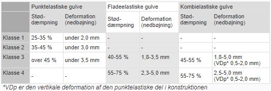
Furthermore, it can be a complicated task to choose the right sports floor, as it often has to take into account both the many different sports that use the hall floor, as well as the other activities for which the hall is used. The European standard EN 14904 applies as a national standard in all the Nordic countries. All sports floors installed in multi-purpose halls (school gymnasiums and sports halls) must comply with this standard. In the standard, a distinction is made between point-elastic, surface-elastic and combi-elastic sports floors. The floors are divided into 4 different classes.
Class 1 and 2 relate to point-elastic sports floors, which are best suited where children under 50 kg exercise physically or for areas where aerobics, table tennis, badminton etc.
Class 3 and 4 relate to flat-elastic and combi-elastic sports floors, which are best suited for larger gymnasiums and sports halls with heavy loads. The best effect of a flat elastic sports floor is achieved for people over 50 kg. Combi-elastic sports floors are recommended in cases where it can be expected that people of all weight classes will be physically active.
Important with even elasticity
Inelastic sports floors cause damage to the body, and excessively soft floors do not provide the necessary stability and balance. Most people who practice ball sports prefer a floor with an even elasticity over the entire floor surface. With the right elasticity (deformation), the forces that are transferred to the body are reduced and thus the risk of e.g. joint injuries.
Proper friction is also important
Low friction lowers skid resistance, while excessively high friction increases the risk of joint and muscle damage.
Different areas of application
When choosing a specialized sports floor that e.g. must both be able to cope with trade fairs and exhibitions, the starting point should be what the floor will mainly be used for.
Include all factors
If a sports floor is to be a successful investment, both functionally and economically, it is necessary to take a number of factors into account. The purchase price should e.g. is held up partly against the ongoing maintenance costs and partly against the lifetime of the floor. In the same way, the choice of function must be balanced against the risks of various sports injuries.
The main characteristics are:
• Slip resistance, which is defined in DS/EN 14904. The frictional ability should preferably be in the range 80-110.
• Shock absorption. The different floor types must be able to absorb shocks from the athlete. For point-elastic floors 25-45%, for surface-elastic floors 40-75% and for combination floors 45-75%.
• Deformation. The floor must not be too soft, but must be elastic and deform for the same reason. Reasonable elasticity will produce deformations of the order of 2.3 to 5.0 mm.
• The energy reflection indicates how quickly a floor springs back. The faster the better. The tension in the floor is measured in m/s.
Ball reflection. At the same time that the floor must be able to absorb shock from the athlete, it must be able to give the ball as much rebound as possible. Measured with a basketball, and must be > 90% with reference to a concrete floor.
• Lifetime depends on floor type, use and maintenance.
• Maintenance and cleaning
Follow the supplier's cleaning and maintenance instructions.
• Reaction to fire is classified according to DS/EN 13501-1.

Sports floors are divided into 3 different construction types:
Flat elastic sports floors. In a surface-elastic floor construction, a larger part of the floor yields to the load. The floor usually has a good elasticity and dew-absorbing capacity. There are different types of construction, and the surface can be, for example, wood, vinyl or linoleum. As a starting point, a flat elastic floor will be able to meet the vast majority of requirements for ball games, gymnastics, mobile stands and other activities such as exhibitions and parties.
Flat elastic sports floor
Point-elastic sports floors only give way just below the load point itself. Usually, the floor is built with soft vinyl or rubber on concrete. A point-elastic floor has more limited applications, but can be used for e.g. gymnastics, aerobics and table tennis. On the other hand, it is unsuitable for virtually all ball games, as well as wheelchair use, exhibitions, mobile grandstands and other events that cause large local loads on the floor surface.
Point elastic sports floor
Combi-elastic sports floors consist of both a surface-elastic subfloor construction and a point-elastic surface, and thus provide a combination of the properties of the two floor types.
Combi-elastic sports floor
The combi-elastic floors have more or less the same limitations as the point-elastic floors due to the floor's soft surface.
Economy
The choice of floor type will of course also depend on the price, with the point elastic floor usually being the cheapest and the combination floor the most expensive.
It is important to assess the total cost of the floor (price of the floor + cleaning and maintenance costs) against the sporting requirements.
CE label
Floor coverings for sports areas must be CE-marked (since 1 February 2008).
The harmonized standard DS/EN 14904 is the basis for the CE marking and applies to production and use in Europe.
The required properties appear in annex ZA in DS/EN 14904:
• Reaction in case of fire
• Friction
• Shock absorption
• Release of formaldehyde
In addition to the standard, national requirements may have been drawn up to the extent necessary to comply with building legislation.
CE marking is not a quality mark, but a harmonized standard sheet that acts as the flooring's travel passport within the European Community.
The manufacturer or dealer importing the floor covering is responsible for the CE marking.
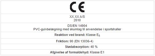

Example of how the CE marking can be used in a product specification
2.4.0.6 Moisture barrier
Moisture in the subfloor is destructive to most floor coverings and you should therefore always measure the moisture level in the subfloor before installing floor coverings. In Denmark, we normally indicate the moisture content of the substrate in %RH (Relative Humidity). The general limit values are 85% RH for resilient floor coverings and carpets and 65% RH for wooden floors. You can read more about building moisture and moisture measurements in the chapter dealing with "Technology and quality" and in the Flooring Industry's folder "Moisture measurement before floor laying". If you find too much moisture in a substrate, it is necessary to clarify whether it is residual building moisture or whether it is a permanent moisture condition. To clarify this, it is usually necessary to carry out several time-shifted measurements. If it is new construction and the moisture percentage falls, it is most likely residual building moisture, if the moisture percentage is constant or increasing, it is rising ground moisture.
Residual building moisture is primarily caused by insufficient drying of the materials that are to form the basis for the floor covering, while rising foundation moisture results from insufficient moisture barrier of the basic construction. Rising ground moisture is rare in modern buildings, if you follow the current instructions for sealing the foundation construction. It is completely different with all-terrain tires in old buildings. With these constructions, there is a real risk that the deck is made without a moisture barrier or that this is damaged, which can result in a permanently high moisture condition in the deck construction.
It is relatively easy to block residual build-up moisture. This can be done by laying out a membrane. The moisture barrier must prevent moisture in underlying constructions from penetrating moisture-sensitive materials in the floor construction. The moisture barrier must therefore be both tight against capillary suction and against water vapor diffusion. The density of the moisture barrier is indicated by its Z-value, the higher the Z-value, the denser the material. In addition, the moisture barrier must be sufficiently robust to withstand handling on the construction site, e.g. withstand being stepped on in connection with laying out the floor.
The requirement for the absolute size of the Z-value depends on the Z-value of the layers above. The moisture barrier must be specified by the designer.
As a rule of thumb, it can be assumed that the Z-value of the moisture barrier must be 5-10 times as high as for the subsequent layers. In practice, meeting the requirements for the Z-value rarely causes problems, because the moisture barriers used, for reasons of robustness, are usually so thick that a high Z-value is achieved.
Commonly used materials for moisture barriers are:
• PE foil, thickness at least 0.15 mm for reasons of robustness. The Z-value for 0.15 mm PE foil is approx. 400 GPa s m2/kg.
• Asphalt cardboard, 2 kg/m2, Z-value approx. 500 GPa s m2/kg
• Molded asphalt, usually laid in a thickness of approx. 25 mm, whereby a Z value of over 1000 GPa s m2/kg is achieved.
• Epoxy system with documented functionality, e.g. according to the Swedish SP method 1310 (Statens Provningsanstalt).
• Special putty compounds
Always follow the suppliers' instructions and product information.
It must be ensured that no perforation of the moisture barrier occurs, for example due to burrs in an underlying concrete layer. Protection of the moisture barrier can be done with an intermediate layer between concrete and moisture barrier. Plastic foil is also a good sliding layer in floating floors, especially if it is used in two layers, or in combination with floorboard or similar products.
2.4.0.7 Underfloor heating
In the eyes of many, underfloor heating provides better comfort than traditional space heating, as the floor becomes warm to walk on. The underfloor heating can be carried out as water-borne systems, i.e. with hot water as a heat source or as electric underfloor heating. Common to all types of underfloor heating systems is that the surface temperature must be adapted to the floor covering. Most types of floor coverings, apart from floor tiles, cannot withstand a surface temperature of more than 25-27oC. This means that the supply temperature must be limited to 30-40oC. To ensure that max. temperature is not exceeded, a floor heating system should always be equipped with a temperature sensor and a limiter. For older and poorly insulated houses, restrictions on the maximum surface temperature can mean that the house cannot be heated by underfloor heating alone and that a supplementary heat source must therefore be established.
Underfloor heating is considered a "building component" and must therefore comply with the Building Regulations applicable at the time of installation. Pay particular attention to the fact that the Building Regulations' rules regarding insulation also apply when installing underfloor heating in existing buildings (remodeling/renovation). This can cause challenges when installing underfloor heating on old all-terrain decks, where it may be necessary to remove the existing flap layer and dig out for insulation that meets contemporary requirements. The requirement for the insulation is expressed in the Building Regulations by a u-value. In table 1, you can find an overview of different insulation materials and the recommended thicknesses they must be laid out in in order to comply with the requirements of the Building Regulations. You can read more about this area at www.bygningsreglementet.dk
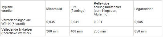
Table 1. BR 15 requirements for insulation of off-road decks U ≤ 0.1 W/m2K
The above table is indicative, always consult the suppliers' instructions when choosing a specific product.
Most floor materials are basically suitable for underfloor heating, but here too there are a number of conditions that must be in place:
• The underfloor heating system should be tested in operation for at least 2 weeks, but must be switched off approx. 2 days before the actual floor laying.
• The moisture conditions in the subfloor must allow the laying of the desired floor covering.
For wood-based substrates, the moisture content of the wood structure should be a maximum of 10%. For cast subfloors, the maximum permissible moisture content will depend on the desired floor covering, for wooden floors typically max 65% RH, for other types of floor covering typically max 85% RH. In addition, be aware that the underfloor heating will change / redistribute the moisture in the subfloor. This is particularly important for newly poured floors. See also Gulvbranchen's brochure "Moisture measurement before floor laying"
Waterborne systems
Waterborne underfloor heating can be divided into heavy and light systems.
• Heavy systems are used as a term for systems that are made up of inorganic materials, eg a concrete deck with cast-in heating hoses.
• Lightweight systems are a term for systems made up of organic materials, such as a slab floor on a wooden beam layer or the heating hoses being in loose polystyrene sheets.
Heavy floor heating systems
• Heavy floor heating systems a term for floor heating systems where heating hoses are embedded in a load-bearing concrete slab, which helps to distribute the heat so that an even surface temperature is achieved over the floor surface. The principle is illustrated in Figure 1a.
Pay attention to the following:
• The thickness of the concrete above the heating pipes should be between 30 and 90 mm and the center distance between the pipes approx. 300 mm for hoses with a diameter of approx. 20 mm.
• The concrete layer should be well insulated downwards.
• The concrete layer must be dried to the maximum moisture level for the floor covering before the floor covering is laid.
• The underfloor heating can be used to accelerate drying, but be aware that there is a redistribution of the moisture and the floor industry's general rules on permissible moisture limits do not apply.
• Always use a self-drying concrete, ie a concrete with a water cement number ≤ 0.4, a traditional "floor concrete" with a water cement number of 0.6 - 0.7 will take several months to dry out to an 85% RH.
• The concrete must often be troweled to achieve a surface on which a floor can be laid. The surface requirements will depend on the chosen type of top coating.
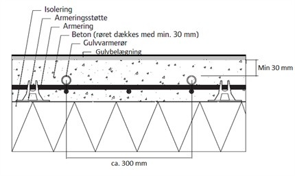 Fig 1 Concrete slab with underfloor heating
Figure 1a: Principle sketch for waterborne underfloor heating embedded in a concrete slab, source Uponor.
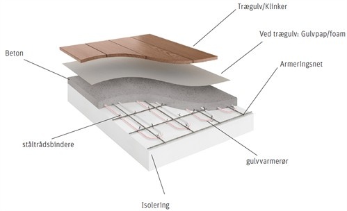
Figure 1b : Waterborne underfloor heating, hoses mounted directly on reinforcing mesh with ties, source Roth.
Renovation systems
There are a number of water-borne underfloor heating systems for embedding in a non-load-bearing layer on top of a load-bearing concrete deck. Compared to the systems described above, they have a significantly lower installation height. This type of water-borne underfloor heating system is primarily used for renovation tasks. The systems are available with installation heights of down to 15-20 mm. In figure 2a+b you can see a picture of a renovation system. These systems typically use thin hoses that are relatively close together and a carrier medium to hold the hoses.
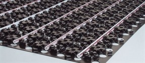
Figure 2a: Waterborne underfloor heating - renovation, source Uponor.
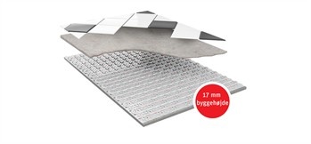
Figure 2b: Waterborne underfloor heating for renovation, installation height 17 mm, source Roth.
Lightweight underfloor heating systems
Floating subfloors with built-in heating hoses. This type of underfloor heating system is characterized by the fact that the heating hoses lie in some grooves in prefabricated chipboard or polystyrene boards. To ensure an even distribution of the heat over the floor surface, metal heat distribution plates are used. On top of the heat distribution plates, a floating floor plate is laid out, which forms a base for the actual floor covering. If lamella parquet is laid out (min. 14 mm thickness) or equivalent, the base plate can be omitted, a 500 g floor board should be used as an intermediate layer.
For this type of system, pay attention to the following:
• That supplier instructions are followed closely.
• The finished floor will have the same flatness as the substrate. It is not possible to putty or otherwise create in the floor surface on top of the underfloor heating plates. The floor industry's general flatness requirement of ± 2mm over a 2 meter straight plank will apply, if nothing else has been agreed. This may mean straightening the subfloor before laying the underfloor heating panels.
• The construction must be laid out floating.
• The floor heating plates are laid out so that they follow the pattern of the hoses, with staggered joints.
• The heat distribution plates must lie firmly in the tracks, they must not tilt, etc.
• The base plates for the floor covering must be laid out across the underfloor heating plates.
Figure 3a+b shows 2 examples of floating constructions with built-in heating hoses.
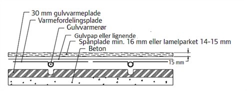
Figure 3a. Example of the floor structure with a 30 mm floor heating plate in polystyrene, source Uponor.
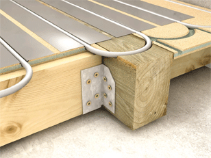
Figure 3b: Example of a floor structure that uses a chipboard as underfloor heating, source Novopan.
Underfloor heating built into a load-bearing floor
The heating pipes are built into a blind floor that is laid out on top of or in between the beams. The location on top of the beams gives a greater installation height, but a significantly simpler construction. For renovation tasks, building in between the beams can often be the only option. Figures 4a&b and 5a&b illustrate the principles.
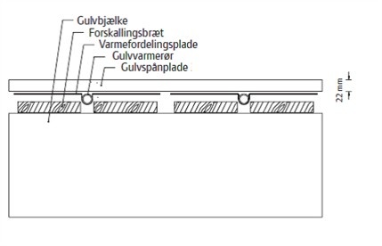
Figure 4a: Principle sketch of underfloor heating laid out in a laminated floor on a beam layer, source Uponor.
.jpg)
Figure 4b. Underfloor heating in laminated flooring on joists.
With this construction, you must pay attention to:
• That the beam layer (joists) has the desired flatness.
• That there is room for the heating hoses to be turned at the walls without weakening the floor.
• That the distance between the beams/beams must be no more than 60 cm (measured from center to centre). If the distance is greater than 60 cm, auxiliary beams must be inserted between the beams.
• Be aware that some types of flooring require a smaller distance between the joists, for example the maximum distance between the joists for clinker laid out on chipboard is 30 cm.
• To comply with the building regulations' requirements for heat loss (insulation), also during renovation tasks. Underfloor heating is considered a new part of the building and must therefore comply with applicable regulations.
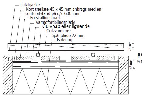
Figure 5a: Principle sketch of underfloor heating laid out in a blind floor between beams, source Uponor.
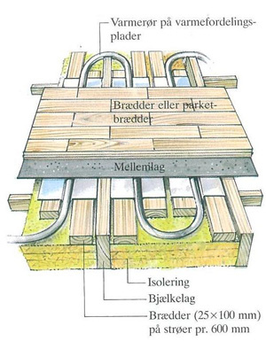
Figure 5b: Underfloor heating in a laminated floor between joists with parquet, source Bolius.
With this construction, you must pay attention to:
• That the distance between the auxiliary beams must be a maximum of 60 cm (measured centre-to-centre).
• That a solution must be found for how the water hoses are routed past the beams. Cutting into the beams should be avoided as the beams weaken.
• Be aware that some types of flooring require a smaller distance between the joists, for example the maximum distance between the joists for clinker laid out on chipboard is 30 cm.
• To comply with the Building Regulations' requirements for heat loss (insulation) also for renovation tasks. Underfloor heating is considered a new part of the building and must therefore comply with applicable regulations.
Electric underfloor heating
A thin electrical conductor (wire) will become hot when a current is passed through it. Electric underfloor heating utilizes this principle. The conductor can either be cast into a concrete floor or laid under a wooden floor / slab floor in the same way as water-based underfloor heating.
Rules for electric underfloor heating
In general, it is not legal to establish electricity as the primary heating source in a house located in an area that is supplied with either gas or district heating.
However, there are exceptions, and electric underfloor heating may be used:
• If there was already electric heating in your home in 1994, when the rules came into force.
• Extension to a house with electric heating, where a completely new heating system is not established.
• If there are technical construction conditions which make it disproportionately expensive to install a more environmentally friendly heat source.
• As a supplementary heat source, for example for heating outside rooms, attics or rooms that are rarely used.
• In summer houses, holiday homes, allotment houses, etc
• Limited electric heating in bathroom floors, so-called comfort heating.
• The house is built in low energy class 1 and 2.
Advantages and disadvantages of electric underfloor heating
Advantage:
• The floor is comfortable and warm to walk on.
• The floor can also be hot in summer.
• It is easy and cheap to install.
• Low installation height approx. 10 mm.
• It does not take up much height, and can often be laid on top of an existing floor.
• It gets hot quickly compared to water-based underfloor heating.
Disadvantages:
• Electric underfloor heating is two to three times as expensive to operate as water-based underfloor heating.
• Electric underfloor heating does not counteract cold fall at windows (water-based underfloor heating does not either).
• If electric heating cables with too much output are chosen, or if the cables are laid closer than prescribed, the floor can become very hot, as the thermostat cannot keep up and shut off the heat.
• If the electric underfloor heating system breaks, it is expensive and difficult to repair, as the floor has to be broken up (this can also be the case with waterborne underfloor heating)
You can install electric underfloor heating on top of concrete and on floor slabs on wooden battens (joists).
The electrical conductors are often attached to a net, so-called mats, which are rolled out where the heat in the floor is to be. The mats are about 3-4 mm thick. When embedding, the mats must be attached to the subfloor and plastered over so that the mats are completely covered. Be careful with the attachment to the subfloor, if the mats are not properly attached, they can be placed on top of the putty layer, necessitating an additional putty. Always have the heating network checked by an electrician before flooring is installed. Electric underfloor heating can be installed under most types of floor covering.
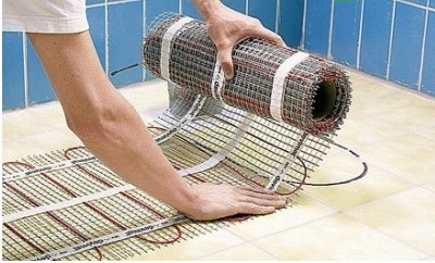
Figure 6: Laying of electric underfloor heating network
References: The flooring industry's publication "Floors and floor heating"
Sources: Uponor installation manual-floor heating, Gulvfakta.dk, Heat-com.
2.4.0.8 Installation floors
Installation floors.
Installation floors are also often called double floors or computer floors. In the past, this type of flooring was used in very technically heavy premises, but the construction is gaining ground in modern office buildings, with large offices and requirements for flexibility, in layout and use. Installation floors consist of loose, demountable floor slabs. The slabs lie on some form of substrate that raises the slabs above the subfloor, thereby creating a cavity in which larger or smaller installations can be moved into the space. The supporting substructure can be supplied with fixed or adjustable legs in heights between approx. 37 (renovation floors) and 2000 mm.
A distinction is made between:
• Cable routing floors, which are made with heights from approx. 37 mm up to approx. 120 mm. They cannot be adjusted in height and therefore require a flat surface. Access to the cavity in the finished floor requires, for some products, the use of tools.
• Double floors, which are made with adjustable legs up to heights of 2000 mm. There are no special requirements for the surface, as unevenness can be accommodated due to the adjustable legs. Access to the cavity to the finished floor is easy.
There are countless varieties on the market and it can often be difficult to distinguish them from one another. In what follows, the characteristics of the main groups are reviewed
Cable routing floors
Cable routing floors, made in heights up to 120 mm. They cannot be adjusted in height and therefore require a flat surface. Access to the cavity in the finished floor requires, for some products, the use of tools.
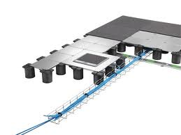
Figure 1: Example of a cable guide wolf. The substructure is made of plastic columns that stand loosely on the floor. The floor plates are made of sheet steel.
The floor plates for the cable routing floors are made of galvanized steel plates that are bent at the edges to give the necessary strength. As flooring for cable routing floors, products that can lie loose or possibly fixed with a staple adhesive, making carpet tiles the most frequently used floor covering for cable routing floors. If carpet tiles with a magnetic backing are used, they can be laid without using glue. A single manufacturer can supply the boards with wooden cladding in the form of a 14 mm lamella parquet.
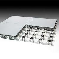
Figure 2: Example of a cable routing floor with the substructure made of bent steel plate that is glued to the subfloor.
The cable routing floors are not covered by EN12825. But in general, the suppliers have tested the products in accordance with the subtests from EN 12825 that are relevant to the product.
In general, they comply with the following specifications:
• Installation height: 37 - 120 mm
• Point load: Max permissible 10 KN (tread surface 25 x 25 mm)
• Deflection <2.4 mm v. 3 KN
• Fire class: Bfl-S1 in accordance with EN 135101-1
• Electrically conductive as required.
Double floors
Double floors must comply with the requirements of EN12825.
EN12825 defines 6 load classes and two levels for the safety factor, see also table 1.
According to EN12825, the point load has an area of 625 mm² (equivalent to 25 x 25 mm).
Table 1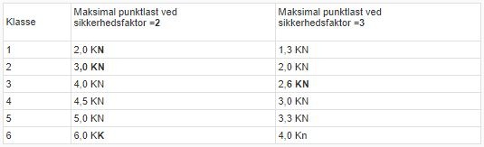
As a general rule, it is recommended to use safety factor 3
EN12825 also defines the maximum deflection for the floors (see table 2).
Table 2.
The deflection is measured by the nominal working load, which is calculated by dividing the ultimate load by the safety factor. (Fn = Fu/S). It operates with 2 safety factors. 2 and 3. EN12825 also determines the strength of the columns. The columns must, in their maximum length, be able to withstand a load of at least 4 times the nominal working load.
Floor tiles
The floorboards are an essential part of installation floors and are decisive for many of the properties of the finished floor.
The floorboards are normally supplied in thicknesses of 30 and 38 mm.
The desired floor covering is glued to the front. The installation of the floor covering is best done at the factory and there are in practice very few restrictions in the choice of top covering. The back side must be provided with a barrier, which usually consists of a foil or plate in steel or aluminium. The purpose of the barrier is to ensure tension equilibrium between the front and back, so that the plates do not bend.
The edges must be protected by a PVC strip.
The floorboards can be divided into two main groups:
• Floor boards made of organic material and floor boards made of inorganic material.
• Floor boards made of organic material are often made of high-quality chipboard with a density of at least 700 kg/m3.
• Inorganic floor slabs are often made from mineral materials such as calcium sulphate or metal, steel or aluminium. The steel plates can be supplied with different perforations so that the room can be ventilated via the floor.
• For very special purposes, glass plates can be supplied.
• Plates can be combined. This allows for optimized properties and economy.
• The material of the floorboards determines their fire properties.
Table 3 provides an overview of the fire classes and the construction of the boards.
Table 3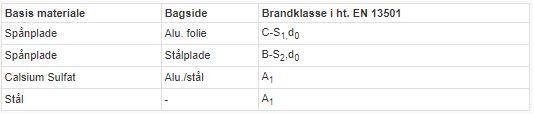
Surfaces.
The floorboards can be supplied with virtually any type of floor covering, from soft carpet coverings to hard coverings such as stone or metal.
The most used coatings are:
• Linoleum
• Vinyl
• Rubber
• Carpets
• Wood (parquet)
For the carpets, velor products are more suitable end loop products. And it is recommended that, when choosing carpeting, you think through the interaction with any pattern reports and the module of the floorboards. In addition, it is recommended that you use coatings that do not thread in cuts. In a similar way, one must be careful when using elastic coverings with a highly structured surface and/or very distinctive patterns, as the pattern (structure) may be difficult/impossible to fit onto the module of the boards.
Factory-fitted coverings usually work best, as the edge sealing can only be done manually with difficulty.
The floorboards can be supplied with conductive/antistatic floor coverings. You can read more about this in the section on conductive and antistatic floor coverings.
The substructure
The main component of the substructure is the column (often called a leg) that supports the floor slab. The material and design of the column is very important in relation to the strength of the floor. It is recommended that you choose systems with steel columns and that you ensure that the top and base plates are sufficiently rigid. The length of the columns must be adjustable (within certain tolerances), whereby inaccuracies in the subfloor can be compensated for. The length of the column must be able to be locked/fixed when it is finally adjusted so that it does not change in the operating situation. The columns must be protected from corrosion, e.g. by hot-dip galvanizing, etc. processes. The columns can possibly are connected horizontally to traverses, struts that are mounted between the heads of the columns.
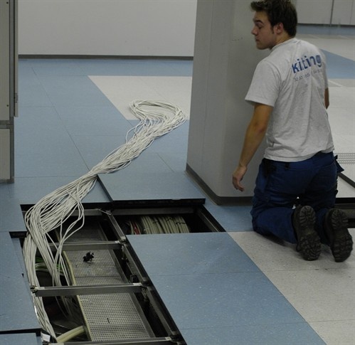 Figure 3: Double floor with sleepers
At heights above 500 mm, cross members must be fitted between the columns. For lower floors, it will depend on the use of the floor. Depending on the use of the floor, the traverses can be screwed firmly or placed loosely between the column heads. If there is a need for floors with particularly high bearing capacity and very high strength, the traverses can be designed as determined steel beams - C-shaped steel profiles - which are screwed to the heads. The floor slabs are placed on top of the steel beams. This type of floor is sometimes called kraft flooring.
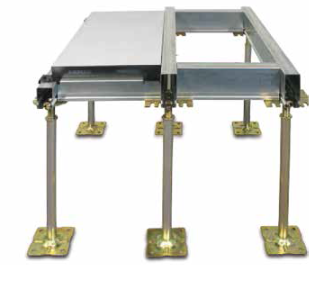
Figure 4: Image of kraft floor
If you need further information, we can refer to Gulvbranchen's information leaflet on installation floors.